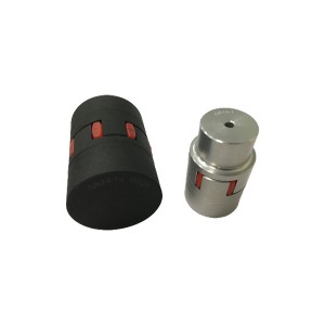
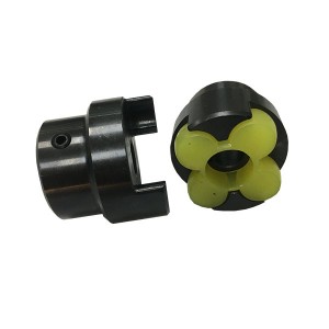
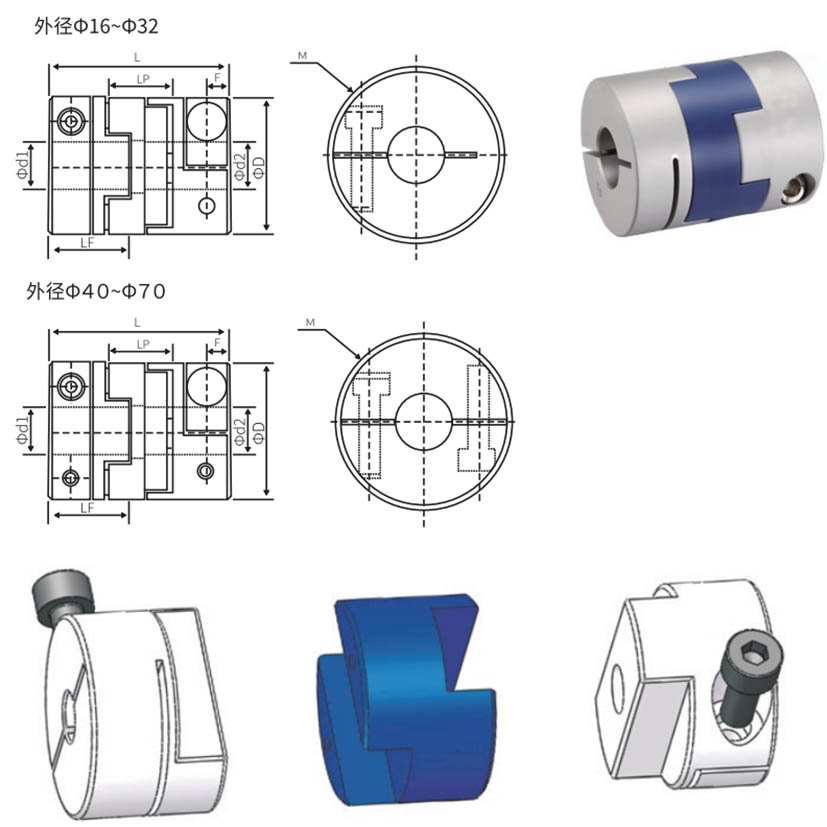
Oldham-Kupplungen, Körper AL, elastisch PA66


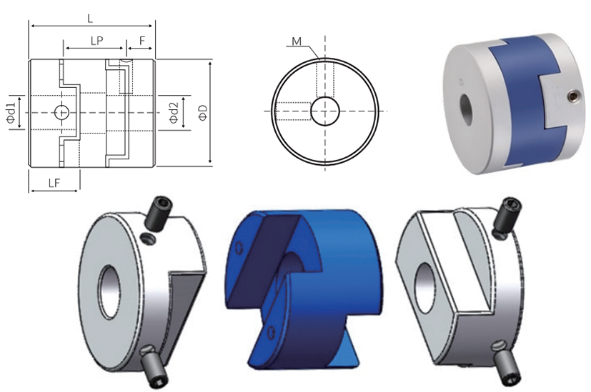
| Dimensionstabelle | mm | |||||||
| Modell | Gemeinsame DL / D2 Innendurchmessergröße | ΦD | L | LF | LP | F | M | Anzugsdrehmoment (nm) |
| GL-16X18 | 4-5-6-6,35-7-8 | 16 | 18 | 7.1 | 12 | 3.0 | M3 | 1.2 |
| GL-20X23 | 5-6-6,35-7-8 | 20 | 23 | 9 | 12.7 | 4.5 | M4 | 1.7 |
| GL-20X25 | 5-6-6,35-8-9-9,525-10 | 20 | 25 | 10.1 | 12.7 | 3.0 | M4 | 2.5 |
| GL-25X28 | 5-6-8-9-9.525-10-11-12-14 | 25 | 28 | 21 | 17,7 | 2.8 | M4 | 2.5 |
| GL-32X33 | 5-6-8-9-9.525-10-11-12-12.7-14-15-16 | 32 | 33 | 14 | 20 | 3.4 | M4 | 2.5 |
| GL-40X32 | 8-9-9.525-10-11-12-12.7-14-15-16-17-18-19-20 | 40 | 32 | 14 | 20.3 | 3.2 | M4 | 2.5 |
| GL-44X46 | 8-9-9.525-10-11-1212.7-14-15-16-17-18-19-20-22 | 44 | 46 | 20,7 | 18.4 | 3.5 | M5 | 5 |
| GL-50X38 | 10-12-12.7-14-15-16-17-18-19-20-22-24-25 | 50 | 38 | 16,5 | 22.35 | 3.8 | M5 | 5 |
| GL-55X57 | 10-12-12,7-14-15-16-17-18-19-20-22-24-25-28-30-32 | 55 | 57 | 26.2 | 25,8 | 7.8 | M5 | 5 |
| GL-63X47 | 14-15-16-17-18-19-20-22-24-25-28-30-32 | 63 | 47 | 21 | 25,8 | 6,0 | M6 | 8 |
| GL-70X77 | 16-17-18-19-20-22-24-25-28-30-32-25-38-40 | 70 | 77 | 37 | 25 | 13.5 | M8 | 20 |
Technische Parameter
| Technische Parameter | mm | |||||||
| Modell | Nenndrehmoment (Nm) | Zulässige Exzentrizität (mm) | Zulässiger Ablenkwinkel (∠。) | Zulässige axiale Abweichung (mm) | Zulässige Drehzahl (U/min) | Statische Torsionssteifigkeit (Nm/rad) | Trägheitsmoment (Nm) | Kupplungsgewicht (g) |
| GL-16X18 | 0,7 | 0,8 | 3 | ±0,2 | 9000 | 30 | 3,0 x 10⁻⁷ | 6 |
| GL-20X23 | 1.2 | 1,5 | 3 | ±0,2 | 3100 | 60 | 1,0 x 10⁻⁶ | 14 |
| GL-20X25 | 1,25 | 1.2 | 3 | ±0,2 | 7000 | 58 | 3,0 x 10⁻⁷ | 18 |
| GL-25X28 | 2 | 1.6 | 3 | ±0,2 | 6000 | 130 | 2,8 x 10⁻⁶ | 25 |
| GL-32X33 | 4.5 | 2 | 3 | ±0,2 | 4800 | 270 | 8,9 x 10⁻⁵ | 44 |
| GL-40X32 | 9 | 2.4 | 3 | ±0,2 | 3600 | 520 | 2,1 x 10⁻⁵ | 81 |
| GL-44X46 | 12 | 2.8 | 3 | ±0,2 | 3500 | 560 | 3,8 x 10⁻⁵ | 136 |
| GL-50X38 | 19 | 2.6 | 3 | ±0,2 | 3000 | 800 | 6,0 x 10⁻⁵ | 142 |
| GL-55X57 | 22 | 3.3 | 3 | ±0,2 | 2800 | 795 | 9,9 x 10⁻⁵ | 255 |
| GL-63X47 | 33 | 3 | 3 | ±0,2 | 2500 | 1200 | 2,1 x 10⁻⁴ | 320 |
| GL-70X77 | 56 | 3.8 | 3 | ±0,2 | 2500 | 1260 | 3,9 x 10⁻⁴ | 445 |
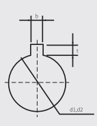
Vergleichstabelle der Keilnutbearbeitungsmaße
| Wellendurchmesserabmessung | Standard-Bearbeitungsmaß der Passfedernut | Keilnutgröße | Standardzeichnung der Keilnutbearbeitung | |||
| dl/d2 | b | t | (bxh) |
| ||
| Schlitzbreite | Toleranz | Schlitztiefe | Toleranz | |||
| Φ6-Φ7.9 | 2 | ±0,0125 | 1.0 | ±0,10 | 2X2 | |
| Φ8-Φ10 | 3 | ±0,0150 | 1.4 | 3X3 | ||
| Φ10.1-Φ12 | 4 | 1.8 | 4X4 | |||
| Φ12.1-Φ17 | 5 | 2.3 | 5X5 | |||
| Φ17.1-Φ22 | 6 | ±0,0180 | 2.8 | 6X6 | ||
| Φ22.1-Φ30 | 8 | 3.3 | ±0,20 | 8X7 | ||
| Φ30.1-Φ38 | 10 | ±0,0215 | 3.3 | 10X8 | ||
| Φ38.1-Φ44 | 12 | 3.8 | 12X8 | |||
| Φ44.1-Φ50 | 14 | 4.3 | 14X9 | |||
| Φ50.1-Φ58 | 16 | 4.4 | 16X10 | |||
| Φ58.1-Φ65 | 18 | 4.4 | 18X11 | |||
Umrissmaßtabelle
| Umrissmaßtabelle | mm | |||||||
| Modell | Gemeinsame DL / D2 Innendurchmessergröße | ΦD | L | LF | LP | F | M | Anzugsdrehmoment (nm) |
| GLC-16X29 | 4-5-6-6.35 | 16 | 29 | 12,5 | 12 | 3 | M2.5 | 0,8 |
| GLC-20X33 | 5-6-6,35-7-8 | 20 | 33 | 14.1 | 12.7 | 3.8 | M2.5 | 0,8 |
| GLC-25X39 | 5-6-6,35-8-9-9,525-10-11-12 | 25 | 39 | 16.9 | 17,7 | 3.9 | M3 | 1.2 |
| GLC-32X45 | 5-6-8-9-9.525-10-11-12-12.7-14-15-16 | 32 | 45 | 20 | 20 | 4.5 | M4 | 2.5 |
| GLC-40X50 | 8-9-9.525-10-11-12-14-15-16-17-18-19 | 40 | 50 | 23 | 20.3 | 5.5 | M5 | 5 |
| GLC-44X46 | 8-9-9.525-10-11-12-14-15-16-17-18-19-20-22 | 44 | 46 | 20,7 | 18.4 | 7 | M5 | 5 |
| GLC-50X53 | 10-11-12.7-14-15-16-17-18-19-20-22-24 | 50 | 53 | 24.2 | 22.35 | 7,5 | M6 | 8 |
| GLC-50X58 | 10-11-12.7-14-15-16-17-18-19-20-22-24 | 50 | 58 | 26,5 | 22.35 | 6.3 | M6 | 8 |
| GLC-55X57 | 10-11-12.7-14-15-16-17-18-19-20-22-24-25-28 | 55 | 57 | 26.2 | 25,8 | 6.3 | M6 | 8 |
| GLC-63X71 | 14-15-16-17-18-19-20-22-24-25-28-30-32 | 63 | 71 | 32,8 | 26.2 | 7.8 | M8 | 20 |
| GLC-70X77 | 14-15-16-17-18-19-20-22-24-25-28-30-32-35-38 | 70 | 71 | 37 | 25 | 7.7 | M8 | 20 |
Technische Parameter
| Technische Parameter | mm | ||||||||
| Modell | Nenndrehmoment (Nm) | Zulässige Exzentrizität (mm) | Zulässiger Ablenkwinkel (∠。) | Zulässige axiale Abweichung (mm) | Zulässige Drehzahl (U/min) | Statische Torsionssteifigkeit (Nm/rad) | Trägheitsmoment (Nm) | Kupplungsgewicht (G) | |
| GLC-16X29 | 0,7 | 0,8 | 3 | ±0,2 | 9000 | 30 | 3,5 x 10⁻⁷ | 12 | |
| GLC-20X33 | 1..2 | 1.2 | 3 | ±0,2 | 7000 | 58 | 1,5 x 10⁻⁶ | 19 | |
| GLC-25X39 | 2 | 1.6 | 3 | ±0,2 | 6000 | 130 | 3,2 x 10⁻⁶ | 35 | |
| GLC-32X45 | 4.5 | 2 | 3 | ±0,2 | 4800 | 270 | 1,5 x 10⁻⁵ | 67 | |
| GLC40X50 | 9 | 2.4 | 3 | ±0,2 | 3600 | 520 | 4,2 x 10⁻⁵ | 114 | |
| GLC-44X46 | 12 | 2.5 | 3 | ±0,2 | 3500 | 800 | 4,5 x 10⁻⁵ | 140 | |
| GLC-50X53 | 19 | 2.6 | 3 | ±0,2 | 3000 | 800 | 1,0 x 10⁻⁴ | 190 | |
| GLC-50X58 | 19 | 3 | 3 | ±0,2 | 3000 | 800 | 1,1 x 10⁻⁴ | 215 | |
| GLC-55X57 | 25 | 3.2 | 3 | ±0,2 | 3000 | 900 | 1,3 x 10⁻⁵ | 260 | |
| GLC-63X71 | 33 | 3 | 3 | ±0,2 | 2550 | 1200 | 3,5 x 10⁻⁴ | 455 | |
| GLC -70X77 | 56 | 3.5 | 3 | ±0,2 | 2500 | 1260 | 4,1 x 10⁻⁴ | 520 | |
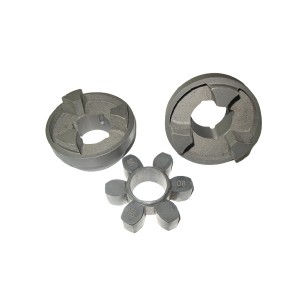
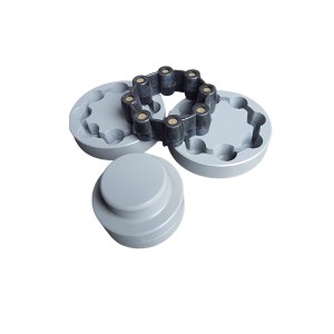
Oldham-Kupplungen sind dreiteilige, flexible Wellenkupplungen, die zur Verbindung von Antriebs- und Abtriebswellen in mechanischen Kraftübertragungsbaugruppen dienen. Flexible Wellenkupplungen dienen dazu, die unvermeidliche Fehlausrichtung zwischen verbundenen Wellen auszugleichen und in manchen Fällen Stöße zu absorbieren. Material: Die Uubs bestehen aus Aluminium, der elastische Körper aus PA66.